

ZA 3510 Installation manual EN (pdf)
ZA 3510 Installation manual EN (pdf)
Description: ZA 3510 Installation manual EN
Access level: end-user
Reference: SDOC-498608282-1042
Download: PDF
Access level: end-user
Reference: SDOC-498608282-1042
Download: PDF
www.sensolus.com | info@sensolus.com
October 24, 2024 9:58 AM
Installation and activation manual ZA 3510
Put the cable onto the connector.
Only the black plastic piece will go
into the connector. Do not force this
Tighten the connection by gently
screwing the cable into the connector.
Do not force this as well.
Guidelines for mounting the tracker can be found in the Sensolus documentation center.
Installing the the zone anchor
Activation of the zone anchor
Hold a magnet for about 5
seconds on top of the logo on the
zone anchor.
You will first see a red LED. Do
not remove the magnet yet.
When the green LED is blinking
you can remove the magnet. The
zone anchor is ready for use.
Attach the zone anchor on the wall
Power the zone anchor.
Plug into the netpower
Activation of the zone anchors is preferably done with clear skies, and not inside (e.g. factory or warehouse).
Zone anchors are not activated when delivered to your premises. Their subscription in the platform will start within six month of purchase.
Check if the power cable is connected
well.
The zone anchor can operate independently on its internal battery or you can connect the zone anchor to
the standard electrical network using a power cable and adapter.
If you use the internal battery you can skip this.www.sensolus.com | info@sensolus.com
October 24, 2024 9:58 AM
General installation advice
Avoid blocking the tracker’s view
with thick metal or carbonfibre
walls. They weaken or block the
radiofrequency signals.
Install the tracker vertically, with
the logo facing up.
Place the tracker around 3 meter
high on a wall to ensure scanning coverage. Concrete has an impact on the range of Bluetooth signals. Water absorbs the Bluetooth signals, Large amounts of water will impact the range and detectability of the zone anchor Place the tracker around 3 meter
high on a wall to ensure scanning coverage. Concrete Water Metal Conditions and surrounding materials Anchor placement for zone detectionwww.sensolus.com | info@sensolus.com October 24, 2024 9:58 AM Troubleshooting the zone anchor
- Put the magnet on the zone anchor for less than 5 seconds
- The possible LED feedback options are: Red LED: Zone anchor is not activated Green LED: Zone anchor is activated and working properly No LED: Zone anchor is not functioning (probably dead battery -> contact support) Red LED is blinking: Zone anchor is busy Force new configuration download on the zone anchor Hold a magnet for about 5 seconds on top of the logo on the zone anchor. You will see a green LED. You will see a red and green LED. Now remove the Magnet Green LED is blinking for minimum 30 seconds. Checking for new configurations You see a green LED: New configuration setting received You see a red LED: No new configuration received. A firmware can be uploaded on the zone anchor. Queue the firmware in the Sensolus platform first.
EOL TRACK1210 ZA3510 notice (pdf)
EOL TRACK1210 ZA3510 notice (pdf)
Description: End-of-life notification for the TRACK 1210 and ZA 3510
Access level: partner
Reference: SDOC-498608282-1318
Download: PDF
Access level: partner
Reference: SDOC-498608282-1318
Download: PDF
Ghent, 12/dec, 2025
Dear Partner, Valued Customer,This letter is the official notification that the following products will be discontinued as
detailed below:Product types:
TRACK 1210 Vehicle tracker with external power option (NB-IOT only) ZA 3510
Zone Anchor with external power option (NB-IOT only)Reason / background: End-of-Life of the product has been decided by product management. They are replaced by the NB-IOT/LTE-M combo products (see below).Replacement products: TRACK 1215 Vehicle tracker with external power option (NB-IOT/LTE-M) ZA 3515
Zone Anchor with external power option (NB-IOT/LTE-M)Thank you for reviewing the above information. Should you have any questions, please contact the Sensolus representative in your area.Johan Criel
CTO and Product Lead at Sensolus
ZA 3510 (pdf)
ZA 3510 (pdf)
Description:
Access level: public
Reference: SDOC-498608282-1348
Download: PDF
Access level: public
Reference: SDOC-498608282-1348
Download: PDF
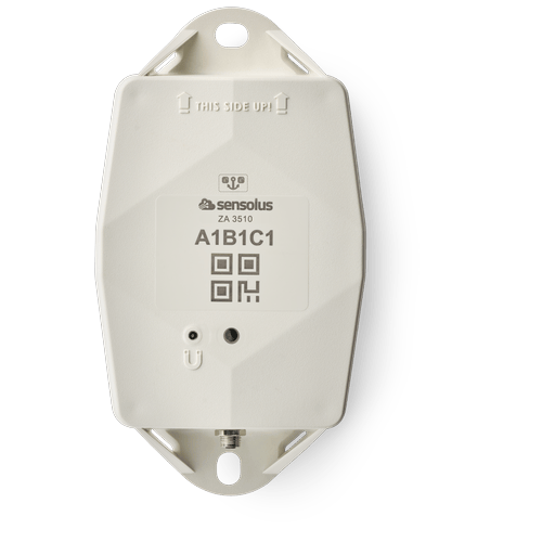
ZA 3510
Zone anchor - battery or net powered - NB-IoT EU & US (without power adapator)
www.sensolus.com | info@sensolus.com
The externally powerd zone anchor with back up
battery for localization of assets equiped with
Bluetooth tag trackers in a dedicated zone. The zone
anchors scans continioulsly when net powered.
Installed at a fixed location
Scans Bluetooth Low Energy tag trackers
NB-IoT
Europe and North America
Back up battery
IP67
Flame retardant
IK 09
Net powered
130×72×36 mm
212g
Connectivity
NB-IoT
•
Energy efficient transceiver
•
Internal omnidirectional antenna
•
Bi-directional communication
•
NB-IoT bands: Europe/North America
•
Data recovery
•
OTA firmware upgrade (NB-IoT)
Bluetooth Low Energy (BLE)
•
Bluetooth Low Energy 5.0
•
Over the air firmware upgrade (BLE)
Activation and mounting
•
Activation manual
•
Holes 7x9mm (⁹/₃₂ * ²³/₆₄ in) for screws or rivets. 115 mm
(4¹⁷/₃₂ in) distance between the centers of the mounting
holes.
•
Instructions for mounting the device are available in the
Sensolus documentation center.ZA 3510
Zone anchor - battery or net powered - NB-IoT EU & US (without power adapator)
www.sensolus.com | info@sensolus.com
Mechanics & Design
Antennas
All antennas are internal
Water & dust resistance
IP67
Size
130x72x36 mm
(5⅛ x 2⁵³⁄₆₄ x 1²⁷⁄₆₄ in)
Impact resistance
IK09
Weight
218 gram (7.68 oz)
Drop shock and vibration
EN 60068
Color
White
Operating temperature
-20°C to 60°C
(-4°F to 140°F)*
The specifics regarding operational temperature are contingent upon the
application, installation circumstances, and environmental factors such as
sunlight exposure. For further information, please reach out to Sensolus.
Battery life can be affected when devices function for extended periods at the
extremes of this range.
Casing
•
PBT/PC 29 TM-Z2 FR UV LS
•
Flame retardant
•
UV-stabilized
Power supply
•
220-230 V Europe
•
110-115 V North America
•
Power supply cable length 2 meter
•
AES encrypted firmware
•
Firmware upgrade allows only signed firmware images
Back up battery
Back up battery lifetime when scanning
Utilize the Sensolus battery calculator to assess the lifespan of
the backup battery, which varies based on the specific use
case.
Back up battery characteristics
•
User replaceable battery pack (Li-SoCl2) 12000 mAh
•
2.94 gram (0.1037oz) lithium
Certifications
Regulatory
•
CE
•
FCC
•
IC
Bluetooth 5.0
Declaration ID D068598
Environmental
IK9
Electrical safety
EN 62368-1ZA 3510
Zone anchor - battery or net powered - NB-IoT EU & US (without power adapator)
www.sensolus.com | info@sensolus.com
User Interaction
Device activation
Magnetic activation
LED feedback
Green & red LED feedback on the device
Synchronize remote settings
•
Instant: Magnet activation
•
Periodic: No user interaction needed
Management Services
Diagnostics
•
Battery lifetime prediction
•
Detailed energy consumption
•
Geolocation diagnostics
•
Installation
•
Communication quality
Management
•
OTA firmware updates over NB-IoT and BLE
•
Remote configuration
•
Zone anchor localization with Sensolus smartphone app
Application services
•
Bluetooth tag tracker scanning
•
Act as managed geobeacon
Tag tracking scanning
•
Bluetooth tag tracker scanning
•
Act as managed geobeacon
Discuss with Sensolus when more than 2000 Bluetooth tag trackers need to be
scanned at once
Firmware configuration
Bluetooth tag tracker scanning configurations
•
Scan and send interval
•
Bluetooth tag tracker’s RSSI scan treshold
•
Filter scanned Bluetooth tag trackers on UUID
Use as geobeacon
Enabled or disabled
Security
•
Device unique encryption keys
•
End to end payload encryption Chacha 20
•
AES encrypted firmware
•
Firmware upgrade allows only signed firmware images
Accessories
The ZA 3510 does not ship with a power adaptor. Sensolus
has power adaptors for EU, UK and USA.
•
ADPT 8500 EU - ZA 3510 net power adaptor EU version
•
ADPT 8501 UK - ZA 3510 net power adaptor UK version
•
ADPT 8502 US - ZA 3510 net power adaptor US version
Power adaptor Europe (pdf)
Power adaptor Europe (pdf)
Description: Power adaptor Europe
Access level: public
Reference: SDOC-498608282-1058
Download: PDF
Access level: public
Reference: SDOC-498608282-1058
Download: PDF
October 24, 2025 11:06 AM
www.sensolus.com | info@sensolus.com
Net power adaptor EU version
ADPT 8500 EU
100 - 240 V
50/60 Hz
Power input
Voltage
Frequency
Power adapter featuring a power plug designed for use in
mainland Europe, complete with a 2-meter long cable.
IP 67 connector to ZA 3510
Europe
Certifications
0,18 A
Current
CE
Europe
Mechanics & design
Size
55.1 x 24.1 x 35.5 mm
Color
White
wall-mount, 2 pin, EU
Input plug
0°C to 50°C
Operating temperature
0,1 W
No load power consumption
Yes
RoHS
Cable
·
UL 2464, 24 AWG
·
2 meter long
Plug
4 pins with screwable M5 connector
Power adaptor USA (pdf)
Power adaptor USA (pdf)
Description: Power adaptor USA
Access level: public
Reference: SDOC-498608282-1060
Download: PDF
Access level: public
Reference: SDOC-498608282-1060
Download: PDF
October 24, 2025 11:06 AM
www.sensolus.com | info@sensolus.com
100 - 240 V
50/60 Hz
Power input
Voltage
Frequency
Power adapter featuring a power plug designed for use in
the USA, complete with a 2-meter long cable.
IP 67 connector to ZA 3510
USA
Certifications
0,18 A
Current
FCC part 15: Class B for radiated and conducted emissions
USA
Mechanics & design
Size
55.1 x 24.1 x 35.5 mm
Color
White
wall-mount, 2 pin, US
Input plug
0°C to 50°C
Operating temperature
0,1 W
No load power consumption
Net power adaptor USA version
ADPT 8502 USA
Yes
RoHS
Cable
·
UL 2464, 24 AWG
·
2 meter long
Plug
4 pins with screwable M5 connector
Power adapter UK (pdf)
Power adapter UK (pdf)
Description: Power adapter UK
Access level: public
Reference: SDOC-498608282-1077
Download: PDF
Access level: public
Reference: SDOC-498608282-1077
Download: PDF
October 24, 2025 11:06 AM
www.sensolus.com | info@sensolus.com
Net power adaptor EU version
ADPT 8501 UK
100 - 240 V
50/60 Hz
Power input
Voltage
Frequency
Power adaptor featuring a power plug designed for use in
UK, complete with a 2-meter long cable.
IP 67 connector to ZA 3510
UK
Certifications
0,18 A
Current
CE
Europe
Mechanics & design
Size
55.10 x 49.50 x 42.49 mm
Color
White
wall-mount, UK
Input plug
0°C to 50°C
Operating temperature
0,1 W
No load power consumption
Yes
RoHS
Cable
·
UL 2464, 24 AWG
·
2 meter long
Plug
4 pins with screwable M5 connector