

ZA 3515 (pdf)
ZA 3515 (pdf)
Description:
Access level: public
Reference: SDOC-498608282-1353
Download: PDF
Access level: public
Reference: SDOC-498608282-1353
Download: PDF
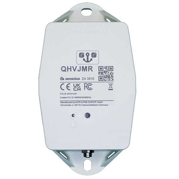
sensolus
ZA 3515
Zone anchor - battery or net powered - NB-IoT/LTE-M
www.sensolus.com | info@sensolus.com
The battery powered zone anchor (with
optional external power adaptor) for
localization of assets equipped with
Bluetooth tag trackers.
Installed at a fixed location
Scans Bluetooth Low Energy tag trackers
NB-IoT
LTE-M
Back up battery
IP67
Flame retardant
IK 09
Net powered
130×72×36 mm
218g
Connectivity
NB-IoT and LTE-M
•
Energy efficient transceiver
•
Internal omnidirectional antenna
•
Bi-directional communication
•
NB-IoT and LTE-M bands: Europe/North America
•
Data recovery
•
OTA firmware upgrade (NB-IoT and LTE-M)
Bluetooth Low Energy (BLE)
•
Bluetooth Low Energy 5.0
•
Over the air firmware upgrade (BLE)
Connectivity plan
•
ZA 3515 comes with the Extended connectivity
plan
Activation and mounting
•
Activation manual
•
Holes 7x9mm (⁹/₃₂ * ²³/₆₄ in) for screws or rivets.
115 mm (4¹⁷/₃₂ in) distance between the centers of
the mounting holes.
•
Instructions for mounting the device are available
in the Sensolus documentation center.sensolus
ZA 3515
Zone anchor - battery or net powered - NB-IoT/LTE-M
www.sensolus.com | info@sensolus.com
Mechanics & Design
Antennas
All antennas are internal
Water & dust resistance
IP67
Size
130x72x36 mm
(5⅛ x 2⁵³⁄₆₄ x 1²⁷⁄₆₄ in)
Impact resistance
IK09
Weight
218 gram (7.68 oz)
Drop shock and vibration
EN 60068
Color
White
Operating temperature
-20°C to 60°C
(-4°F to 140°F)*
The specifics regarding operational temperature are contingent upon
the application, installation circumstances, and environmental factors
such as sunlight exposure. For further information, please reach out
to Sensolus. Battery life can be affected when devices function for
extended periods at the extremes of this range.
Casing
•
PBT/PC 29 TM-Z2 FR UV LS
•
Flame retardant
•
UV-stabilized
Power supply
•
220-230 V Europe
•
110-115 V North America
•
Power supply cable length 2 meter
•
AES encrypted firmware
•
Firmware upgrade allows only signed firmware
images
Back up battery
Back up battery lifetime when
scanning
Utilize the Sensolus battery calculator to assess the
lifespan of the backup battery, which varies based on
the specific use case.
Back up battery characteristics
•
User replaceable battery pack (Li-SoCl2) 12000
mAh
•
2.94 gram (0.1037oz) lithium
Certifications
Regulatory
•
CE
•
FCC
•
IC
Bluetooth 5.0
Declaration ID D068598
Environmental
IK9
Electrical safety
EN 62368-1sensolus
ZA 3515
Zone anchor - battery or net powered - NB-IoT/LTE-M
www.sensolus.com | info@sensolus.com
User Interaction
Device activation
Magnetic activation
LED feedback
Green & red LED feedback on the device
Synchronize remote settings
•
Instant: Magnet activation
•
Periodic: No user interaction needed
Management Services
Diagnostics
•
Battery lifetime prediction
•
Detailed energy consumption
•
Geolocation diagnostics
•
Installation
•
Communication quality
Management
•
OTA firmware updates over NB-IoT,LTE-M and BLE
•
Remote configuration
•
Zone anchor localization with Sensolus smartphone
app
Application services
•
Bluetooth tag tracker scanning
•
Act as managed geobeacon
Tag tracking scanning
•
Bluetooth tag tracker scanning
•
Act as managed geobeacon
Discuss with Sensolus when more than 2000 Bluetooth tag trackers
need to be scanned at once
Firmware configuration
Bluetooth tag tracker scanning
configurations
•
Scan and send interval
•
Bluetooth tag tracker's RSSI scan threshold
•
Filter scanned Bluetooth tag trackers on UUID
Use as geobeacon
Enabled or disabled
Security
•
Device unique encryption keys
•
End to end payload encryption Chacha 20
•
AES encrypted firmware
•
Firmware upgrade allows only signed firmware
images
Accessories
The ZA 3515 does not ship with a power adaptor.
Sensolus has power adaptors for EU, UK and USA.
•
ADPT 8500 EU - ZA 3515 net power adaptor EU
version
•
ADPT 8501 UK - ZA 3515 net power adaptor UK
version
•
ADPT 8502 US - ZA 3515 net power adaptor US
version
ZA 3515 (pdf)
ZA 3515 (pdf)
Description:
Access level: public
Reference: SDOC-498608282-1373
Download: PDF
Access level: public
Reference: SDOC-498608282-1373
Download: PDF
ZA 3515
NB-IoT/LTE-M Zone Anchor
www.sensolus.com | info@sensolus.com
Battery-powered zone anchor for asset localization
using Bluetooth tag tracker scanning. Features NB-IoT
and LTE-M connectivity with optional AC power
adapter support. Includes OTA updates, encrypted
communications, and comprehensive diagnostics.
NB-IoT
LTE-M
Bluetooth Low Energy 5.0
IP67 rated
IK09 impact resistant
Optional AC power adapter
130 × 72 × 36mm
218g (7.68 oz)
Connectivity
Cellular
•
NB-IoT and LTE-M
•
Europe/North America bands
•
Bi-directional communication
•
Internal omnidirectional antenna
Bluetooth
Bluetooth Low Energy 5.0
Capabilities
•
Tag tracker scanning
•
Managed geobeacon functionality
•
OTA firmware updates (NB-IoT, LTE-M, BLE)
Power
Primary Battery
User-replaceable Li-SoCl₂ battery (12,000 mAh, 2.94g lithium)
Optional AC Adapter
•
220-230V (Europe) or 110-115V (North America)
•
2 meter cable
•
0.1W no-load consumption
Physical Characteristics
Dimensions
130 × 72 × 36mm (5⅛ × 2⁵³⁄₆₄ × 1²⁷⁄₆₄ in)
Weight
218 grams (7.68 oz)
Color
White
Material
•
PBT/PC casing
•
Flame retardant
•
UV stabilized
Mounting Holes
7 × 9mm, 115mm center-to-center spacingZA 3515
NB-IoT/LTE-M Zone Anchor
www.sensolus.com | info@sensolus.com
Environmental
IP Rating
IP67
Impact Resistance
IK09
Operating Temperature
-20°C to 60°C (-4°F to 140°F)
Drop Shock and Vibration
EN 60068
Management & Security
User Interaction
•
Magnetic activation
•
LED feedback (green & red)
•
Remote configuration sync
Diagnostics
•
Battery lifetime prediction
•
Geolocation diagnostics
•
Communication quality monitoring
Security
•
Device-unique encryption keys
•
ChaCha20 end-to-end encryption
•
AES encrypted firmware
•
Signed firmware images only
Configuration
Configurable Features
•
Tag scanning intervals
•
Scanning thresholds
•
Remote configuration updates
Certifications
Regulatory
•
CE
•
FCC
•
IC
Electrical Safety
EN 62368-1
Environmental
RoHS compliant, Drop shock testing in progress
Mounting Options
Supported Methods
•
Rivets
•
Bolts/screws
•
Double-sided tape
•
Tie wraps (6mm)
•
MS Polymer glue
•
Magnet mounting kits
Installation and activation manual ZA 3515 (pdf)
Installation and activation manual ZA 3515 (pdf)
Description:
Access level: public
Reference: SDOC-498608282-1406
Download: PDF
Access level: public
Reference: SDOC-498608282-1406
Download: PDF
Installation and activation manual ZA 3515
www.sensolus.com | info@sensolus.com
January 19, 2026 9:47 AM
# Installing the zone achor
Attach the zone anchor on the wall
Guidelines how to mount the tracker can be found here.
Power the zone anchor
The zone anchor can operate independently on its internal battery or you can connect the zone anchor to the standard
electrical network using a power cable and adapter.
If you use the internal battery you can skip this.
Activation of the trackers is preferably done with clear skies, and not inside (e.g. factory or warehouse).
Trackers are not activated when delivered to your premises.
Their subscription in the platform will start within six months of purchase.
1
Put the cable onto the
connector. Only the
black plastic piece will
go into the connector.
Do not force this
→
2
Tighten the
connection by gently
screwing the cable
into the connector.
Do not force this as
well.
→
3
Check if the power
cable is connected
well.
4
Plug into the
netpower.
Activation of the zone anchor
Activation of the zone anchors is preferably done with clear skies, and not inside (e.g. factory or warehouse). Zone anchors are
not activated when delivered to your premises. Their subscription in the platform will start within six month of purchase.Installation and activation manual ZA 3515
www.sensolus.com | info@sensolus.com
January 19, 2026 9:47 AM
1
Hold a magnet for
about 5 seconds on
top of the logo on the
zone anchor.
→
2
You will first see a red
LED. Do not remove
the magnet yet.
→
3
When the green LED
is blinking you can
remove the magnet.
The zone anchor is
ready for use.
General installation advice
Activation of the zone anchors is preferably done with clear skies, and not inside (e.g. factory or warehouse). Zone anchors are
not activated when delivered to your premises. Their subscription in the platform will start within six month of purchase.
Avoid blocking the tracker's view with metal
or carbonfibre walls. They weaken or block
the radiofrequency signals.
Install the tracker vertically, with the logo
facing up.
Place the tracker around 3 meter high on a
wall to ensure scanning coverage.
Conditions and surrounding materials
Concrete has an impact on the range of
Bluetooth signals.
Water absorbs the Bluetooth signals, Large
amounts of water will impact the range and
detectability of the zone anchor.
Metal reflects the Bluetooth signals, Large
amounts of metal will impact the range and
detectability of the zone anchor.
Anchor placement for zone detectionInstallation and activation manual ZA 3515
www.sensolus.com | info@sensolus.com
January 19, 2026 9:47 AM
Force new configuration download on the tracker
1
Hold a magnet for
about 5 seconds on
top of the logo on the
asset tracker. You will
see a green LED.
→
2
You will see a red and
green LED. Now
remove the magnet.
→
3
Green LED is blinking
for minimum 30
seconds. Your tracker
is checking for new
configurations.
→
You see a red LED:
No new
configuration
received.
You see a green
LED: New
configuration setting
received.
Troubleshooting
- Put the magnet on the tracker for less than 5 seconds
- The possible LED feedback options are: Red LED: Tracker is not activated Green LED: Tracker is activated and working properly No LED: tracker is not functioning (probably dead battery -> contact support) Red LED is blinking: Tracker is busy
- This device may not cause harmful interference, and
- This device must accept any interference received, including interference that may cause undesired operation. This equipment has been tested and found to comply with the limits for a Class B digital device, pursuant to Part 15 of the FCC Rules. These limits are designed to provide reasonable protection against harmful interference in a residential installation. This equipment generates, uses and can radiate radio frequency energy and, if not installed and used in accordance with the instructions, may cause harmful interference to radio communications. However, there is no guarantee that interference will not occur in a particular installation. If this equipment does cause harmful interference to radio or television reception, which can be determined by turning the equipment off and on, the user is encouraged to try to correct the interference by one of the following measures: • Reorient or relocate the receiving antenna. • Increase the separation between the equipment and receiver. • Connect the equipment into an outlet on a circuit different from that to which the receiver is connected. • Consult the dealer or an experienced radio/TV technician for help. FCC Caution: Any changes or modifications not expressly approved by the party responsible for compliance could void the user's authority to operate this equipment. This transmitter must not be co-located or operating in conjunction with any other antenna or transmitter. Radiation Exposure Statement: This equipment complies with FCC radiation exposure limits set forth for an uncontrolled environment. This equipment should be installed and operated with minimum distance 20cm between the radiator & your body. This equipment is not suitable for use in locations where children are likely to be present. Industry Canada Statement This device complies with ISED's licence-exempt RSSs. Operation is subject to the following two conditions: This device may not cause harmful interference, and This device must accept any interference received, including interference that may cause undesired operation. Under Industry Canada regulations, this radio transmitter may only operate using an antenna of a type and maximum (or lesser) gain approved for the transmitter by Industry Canada. To reduce potential radio interference to other users, the antenna type and its gain should be chosen so that the equivalent isotropically radiated power (e.i.r.p.) is not more than that necessary for successful communication. RF Exposure Requirements: This equipment complies with Canada radiation exposure limits set forth for an uncontrolled environment. This equipment should be installed and operated with minimum distance 20cm between the radiator and your body. Le présent appareil est conforme aux CNR d' ISED applicables aux appareils radio exempts de licence. L'exploitation est autorisée aux deux conditions suivantes:
- le dispositif ne doit pas produire de brouillage préjudiciable, et
- ce dispositif doit accepter tout brouillage reçu, y compris un brouillage susceptible de provoquer un fonctionnement indésirable. Conformément à la réglementation d'Industrie Canada, le présent émetteur radio peut fonctionner avec une antenne d'un type et d'un gain maximal (ou inférieur) approuvé pour l'émetteur par Industrie Canada. Dans le but de réduire les risques de brouillage radio électrique à l'intention des autres utilisateurs, il faut choisir le type d'antenne et son gain de sorte que la puissance isotrope rayonnée équivalente (p.i.r.e.) ne dépasse pas l'intensité nécessaire à l'établissement d'une communication satisfaisante. Déclaration d'exposition aux radiations: Cet équipement est conforme aux limites d'exposition aux rayonnements du Canada établies pour un environnement non contrôlé. Cet équipement doit être installé et utilisé avec un minimum de 20 cm de distance entre la source de rayonnement et votre corps.