Description: TRACK 1130 spec sheet
Access level: public
Reference: SDOC-498608282-258
Download: PDF
June 12, 2023 4:18 PM www.sensolus.com | info@sensolus.com LYKANER N5 - WIFI - NB-IoT
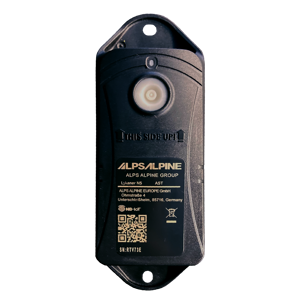
 TRACK 1130 Connectivity Geolocalization 50mm (1 ³¹/₃₂ in) 31,5 mm (1 ¹⁵/₆₄ in) 140 mm (5 ³³/₆₄ in) The long-life battery powered WIFI tracker communicating over the NB-IoT network. Wi-Fi Wi-Fi based geolocalization Sensing Internal · Relocation based on acceleration · Orientation state ∅5,2mm ∅5,2mm (¹³/₆₄ in) 125,35 mm (4 ¹⁵/₁₆ in) · Energy efficient transceiver · Internal omnidirectional antenna · Bi-directional communication NB-IoT IP69 Mechanics & design Water & dust resistance Size 140 x50x31,5 mm (5 ³³/₆₄ x 1 ³¹/₃₂ x 1 ¹⁵/₆₄ in) (L W H) Weight 146 gram (5.15 oz) Color Black Casing PC/PBT -20°C to 60°C (-4°F to 140°F) Operating temperature Antennas All antennas are internal IK8 Impact resistance · NB-IoT bands: Europe and North America · Data recovery · OTA firmware upgrade (NB-IoT) Wi-Fi Up to 7 years of battery life IP69 IK8 NB-IoT Europe and North America Data recoveryJune 12, 2023 4:18 PM www.sensolus.com | info@sensolus.com Certifications Regulatory CE, UK-CA, FCC, IC, CGF, PTCRB User interaction Device activation Activation with button (push hard for at least 5 sec.) LED feedback LED will blink for 10 sec to confirm the activation. Battery · Up to 7 years of battery life depending on the use case. · Not replaceable battery pack: Li-SoCl2,2xER17505M-L 3,6V 5600mAh Management services · Remote configuration · Tracker usage profiles · Low battery alert · 4 battery levels · Communication quality Diagnostics Management Application services · Localization · Geozones Firmware configuration Location service Periodic and relocation parameters Communication service Data recovery configuration (optional) General configuration · Boot methods · Time synchronization Tamper service Virtual tamper algo configuration Security · Device unique encryption keys · End to end payload encryption Chacha 20 · AES encrypted firmware · Firmware upgrade allows only signed firmware images Mounting · Holes ∅5,2mm (¹³/₆₄ in) for rivets · Screws, rivets, or double-sided tape
Description: Installation and activation manual of the TRACK 1130 NB-IOT tracker.
Access level: public
Reference: SDOC-498608282-277
Download: PDF
TRACK 1130 Installation Installation guide of the TRACK 1130 Installation method using bolts
  1. Print the drill hole template (TRACK 1130 drill hole gauge (pdf)) and use it drill hole at the appropriate distances.
  2. Recommended Bolt - M5 X 12mm (Bolt length depends on asset type)
  3. Electric Drill - Torque Setting recommended value is between 1.15 to 1.25 Nm. Installation method using rivets
  4. Use the appropriate size of rivets: 5mm diameter.
  5. Recommended rivets: Gesipa Blind Rivets Aluminium/Steel Standard Flat Head (4,8 x 17mm or 5 x 12mm)
  6. Recommend rivet gun: Gesipa ACCUBIRD PRO Recommended device orientation For optimal battery usage please follow the below device mounting orientation recommendations: Installation advice TRACK 1130 Installation file:///C:/Users/LaurenceClaeys/Documents/SENSDOCU/documentat… 1 of 3 16/03/2023, 11:31
Avoid blocking the tracker’s view with metal or carbonfibre walls. They weaken or block the radiofrequency signals. Make sure the mounting surface is flat and clean, for a strong and durable bond. Place the tracker has high as possible on the asset to ensure good network coverage. Do not install the tracker on parts that receive frequent shocks or vibrations. Avoid placing the tracker in a place that can collect water If your asset is handled in a rough environment, you can place the tracker in a protected location, but never with metal or carbonfibre above the tracker. Tracker activation Trackers are not yet activated when they are delivered to your premises, to avoid battery consumption before actual deployment. The track is a one-time activation device: once it is activated, it cannot be deactivated afterward. The activation status can be verified by looking up the device in the Sensolus Portal using the device serial number. To effectively start using the tracker, it must be activated using the following method: Step 1 Press the activation button and keep it pressed for at least 5 seconds. You can hear or feel a click when the button is effectively pressed. You can also use the blunt back of a pen or pencil for this. Step 2 The red LED will blink for 10 seconds to confirm that is starting the activation sequence. Step 3 Once activation sequence is completed, the device will for a second time emit LED blinking for 5 seconds to indicate the completion of the activation sequence. After activation and during normal operation, the LED does not light up. Tip: Activation of the tracker is preferably done in a place where there are Wi-Fi networks, which makes it easier to confirm that a first Wi-Fi location resolution has succeeded after activation. Tip: The platform subscription costs for the tracker start when it is first activated, or latest after six months after the shipment date. In the (exceptional) case that activation sequence cannot be completed within 3 minutes (for example in areas lacking coverage by the communication provider), the device will employ a temporary back-off strategy to avoid draining the battery (2 x 30 minutes, 12 hours and then 24 hours). This means that TRACK 1130 Installation file:///C:/Users/LaurenceClaeys/Documents/SENSDOCU/documentat… 2 of 3 16/03/2023, 11:31feedback responsiveness may be reduced when encountering this problem. TRACK 1130 Installation file:///C:/Users/LaurenceClaeys/Documents/SENSDOCU/documentat… 3 of 3 16/03/2023, 11:31
Description: TRACK 1130 drill hole template. Use this to drill holes at the correct distances when installing a tracker on an asset.
Access level: public
Reference: SDOC-498608282-264
Download: PDF
125,35 mm Drilling hole pattern for TRACK 1130 Do not scale this drawing! Print on A4 paper
Description: Mounting instructions for installation of Sensolus devices
Access level: public
Reference: SDOC-498608282-1048
Download: PDF
Product mounting advice How to install Sensolus productsLast update: Thursday, June 12, 2025 2Sensolus product mounting advice This document is for all installers of our products and gives an overview and advice for the mounting options of standard Sensolus products.
Choosing the right mounting method is important to make sure the product doesn’t get damaged or falls of.
MOUNTING OPTIONS PER PRODUCT … 3 RIVETS … 4 RIVET DIMENSIONS … 4 THE WAY TO FIND YOUR RIVETS … 5 RIVET MATERIAL … 6 BOLTS AND SCREWS … 7 DOUBLE SIDED TAPE … 8 TIE WRAPS … 9 GLUE … 10 MAGNET MOUNTING KIT … 11 SENSOR AND TAG HOLDERS … 12 MOUNTING ADVICE FOR TRACKERS ON SPECIFIC MATERIALS … 13 VIBRATING PLASTICS IN OUTDOOR CONDITIONS … 13 PLASTIC BOXES … 13 METAL IN OUTDOOR CONDITIONS … 13 Trackers … 13 Tags … 13 FILL LEVEL SENSOR INSTALLATION INSTRUCTIONS … 14 MOUNTING OVERVIEW … 14 TOOLS AND MATERIALS NEEDED … 14 INSTALLATION STEPS … 14
Last update: Thursday, June 12, 2025 3Mounting options per productProduct Rivets Bolts/screws Glue Double sided tape Tie wraps Holder Magnet mounting kit Battery powered trackers• TRACK 1000 ✓ ✓ ✓ ✓ ✓✓ • TRACK 1020 ✓ ✓• TRACK 1030 ✓ ✓• TRACK 1100 ✓ ✓ ✓ ✓ ✓✓ • TRACK 1140 ✓ ✓ ✓ ✓ ✓✓ • TRACK 1110 ✓ ✓ ✓ ✓ ✓• TRACK 1130 ✓ ✓ ✓ ✓ ✓• TRACK 1101 ✓ ✓ ✓ ✓ ✓✓ • TRACK 1141 ✓ ✓ ✓ ✓ ✓Vehicle trackers• TRACK 1203✓ ✓ ✓• TRACK 1210 ✓ ✓ ✓ ✓ ✓Tag trackers• TAG 2001 ✓ ✓ ✓ ✓ ✓• TAG 2002✓ ✓• TAG 2002 ✓ ✓ ✓ ✓ ✓• TAG 2007✓ ✓Sensors• SENSE T 4000✓ ✓• SENSE HT 4050✓ ✓• SENSE M 4201✓ ✓• SENSE T 4004✓ ✓• SENSE FL 4300✓ ✓ ✓ ✓ ✓Infrastructure• GB 3000 ✓ ✓ ✓ ✓• ZA 3500✓ ✓ ✓• ZA 3505 ✓ ✓ ✓ ✓ ✓✓ • ZA 3510✓ ✓Last update: Thursday, June 12, 2025 4 Rivets We recommend rivets because they are easy in installation and strong. Use the appropriate size and length of the rivets. So how to choose the correct dimension of your rivets?
Rivet dimensions
Figure 1: Rivet dimensions D2: 12-14 mm is a good head diameter for 1100/1101 (dome or flat head) D1: 5-6 mm is a good diameter for 1100/1101 L: Rivet body length (decision depends on S) S: Grip range Rivet manufacturers give you the dimensions in D1 x L (e.g. 6 x 20). The rivet manufacturer gives the grip range for the different rivet dimensions that he provides,
e.g. GESIPA Blind rivets alu/steel dome head 6 x 20 has a Grip range of 13,00 - 15,00 mm
Drillhole diameter: D1 + 0,1mm d: Mandrel diameter (needs to fit in your tool, a lot of rivet manufacturer/dealers don‘t have/show this information)
Tracker Thickes 8mm Asset material thickness
Last update: Thursday, June 12, 2025 5 For example: The length of the rivet should be equal to the thickness of both objects you are fastening the tracker to (mounting holes height + thickness material), plus 1.5 times the diameter of the rivet’s stem. Do not use rivets with a smaller diameter, this will not firmly attach the tracker. Do not use rivets with bigger diameter as you might damage the casing. The way to find your rivets • Choose the correct material of the rivet body • Determine the correct grip range (S) by adding tracker material thickness 8mm + material thickness of the asset • Choose your preferred rivet body diameter (5 or 6 mm) • Choose your preferred rivet head diameter (12 or 14 mm) • Make sure the mandrel diameter fits into your rivet tool. If you don’t know the maximum mandrel diameter that your tool can handle, you can determine that by sticking drills with different diameters into your rivet tool. There are often values on the rivet inserts of the riveting tool. These usually refer to rivet body diameters. However, since there are hundreds of different rivet variants on the market and almost every manufacturer does what they want, you should ignore this information and follow the recommendations in this document. Measuring is the best way. Other than others, GESIPA gives you the diameter of the mandrels). • Make sure you have enough drills with correct diameter, it can happen that you will break one or the other drill (rivet body diameter + 0,1mm (e.g. 6,1mm).
GESIPA – The experts in blind riveting: Standard blind rivets
Tracker mount hole Diameters and height overviewProduct Distance between mounting holes Rivet diameter Height of mounting holes TRACK 1110 90 mm 5 mm 5 mm TRACK 1130 125 mm 5 mm 5mm TRACK 1100/1101/1140/1141 115 mm 6 mm 8 mm SENSE FL 4300 111,5 mm 4 mm 5 mm TAG 2001 49 mm 4 mm 3 mm TAG 2006 60 mm 4 mm 7 mm GB 3000 84 mm 4 mm
2 mm ZA 3505 115 mm 5 mm 8 mm
ℹ GESIPA is a good manufacturer of high quality rivets and has a wizard on their website toLast update: Thursday, June 12, 2025 6Rivet material Stainless steel Use Stainless steel rivets when mounting trackers on outdoor assets.Steel Steel rivets can be used for indoor purposes when mounting on steel assets.Aluminium Use aluminum rivets for mountin the tracker on materials such as aluminum, fabrics, plastics, leather,Figure 2 Moun!ng with rivets⚠ Using aluminium rivets on steel can cause the rivet to corrode.
⚠ Do not use stainless steel rivets on aluminium assets. They cause corrosion on the asset . ⚠ Do not use steel rivets on aluminium assets. They can cause corrosion on the asset.
Last update: Thursday, June 12, 2025 7 Bolts and screws Bolts and screws are harder to install than rivets because you need access to both the bolt and the nut. This is not always possible, for example when installing tracker on sidewall of a large container. The advantage of bolts and screws is that it is easier to remove them, rivets/glue/tape is harder.
Using glue in combination with bolts and screws is common practice but requires more work.
  1. Use the appropriate size of screws, see table below. If you don't use the correct sizes you risk damaging the tracker or having an unsafe installa!on.
  2. It is recommended to use thread locking glue on the bolts. Thread locking glue is used to prevent bolts coming lose due to vibra!ons. Pay addi!onal a”en!on to this if you are installing the tracker on a vibra!ng asset. We recommend Loc!te Thread Locker Blue 242.
  3. Protect the tracker casing appropriately: protect the casing with a washer and use a spring washer to mi!gate the effects of vibra!on and temperature varia!ons.
  4. Do not apply more torque than found in the below table. You risk to damage the casing if you exceed it.
Figure 3 Moun!ng with bots and screws Product Distance between holes Bolt type Height of mounting holes Max applied torque TRACK 1110 90 mm M5 5 mm 2.5 Nm TRACK 1130 125 mm M5 5 mm 2.5 Nm TRACK 1100/1101/1140/1141 115 mm M6 8 mm 3.5 Nm SENSE FL 4300 111,5 mm M4 5 mm 3 Nm TAG 2001 49 mm M4 3 mm 2.5 Nm TAG 2006 60 mm M4 7 mmGB 3000 84 mm Comes with the productZA 3505/3510 115 mm M6 8 mm 3.5 Nm ZA 3500 86 mm M4 / /Last update: Thursday, June 12, 2025 8 Double sided tape Double sided tape is easy to install and does not damage the asset unlike bolts/rivets. However you need to be sure both tracker and the surface of the asset are clean. Double sided tape is strong but not so resistant to force applied sideways. Make sure the double sided tap only covers the back of the product. Avoid using double sided tape to attach a tracker or tag on an asset that is regularly exposed to vibrations or shocks. Most products can be mounted with double sided tape. Recommended tapes:
• 3M Acrylic Plus Tape Series PT1000 : h”ps://www.3m.com/3M/en_US/p/d/b40065692/ • 3M™ VHB™ Tape GPH-110GF : h”ps://www.3mbelgie.be/3M/nl_BE/p/d/b40065748 Follow these steps when applying double sided tape:
  1. Make sure the surface of the asset and device are clean and dry.
  2. Sand the surface of the asset.
  3. Sand the backside of the device.
  4. Apply the double sided tape.
  5. Press the device firm onto the asset for a minute.
  6. Let it dry for at least 1 hours before moving the asset.
Figure 4 Moun!ng with double sided tape⚠ TRACK 1020 and TRACK 1030 cannot be mounted with double sided tape. The anti-tamper button needs to be pushed continuously to ensure proper working of the tracker. ℹ SENSE FL 4300 and GB 3000 already have the double sided tape from the factory. ⚠ TAG 2007 can be mounted with double sided tape but be carefull not to tape the battery sloth to the asset so you can still open it to replace the batteriesLast update: Thursday, June 12, 2025 9 Tie wraps We recommend metal tie wraps with a width of 5-6 mm.
In some cases, plastic tie wraps are also useful: if you need to remove the trackers often and fast for example. Take into account that tie wraps can be easily cut to take away the tracker
Product Tie wrap width TRACK 1110 6 mm TRACK 1100/1101/1140/1141 5 mm SENSE FL 4300 / TAG 2001 4 mm TAG 2006 4 mm ZA 3505 6 mmFigure 5 Moun!ng with !e wraps⚠ TRACK 1020 and TRACK 1030 cannot be mounted with tie wraps. The anti-tamper button needs to be pushed continuously to ensure proper working of the tracker.Last update: Thursday, June 12, 2025 10 Glue Glue can be very strong but also once it is glued, it is very hard to remove the device. You will probably damage the device and break warranty when removing a glued device.
Avoid gluing a tracker or tag on an asset that is regularly exposed to vibrations or shocks. Our devices are best paired with these recommended glue types.
Product Glue type TRACK 1100/1110/1140/1101/1141 MS Polymeer SENSE FL 4300 MS Polymeer SENSE T 4000/ SENSE T 4004 / SENSE M 4201
Polyurethane glue TAG 2001 MS Polymeer TAG 2002 Polyurethane glue TAG 2006 MS Polymeer TAG 2007 MS Polymeer Apply these steps when using glue
  1. Make sure the surface of the asset and device are clean and dry.
  2. Sand the surface of the asset.
  3. Sand the backside of the device.
  4. Apply the glue to the sanded surface.
  5. Press the device firm onto the asset for a minute.
  6. Let it dry for at least 6 hours before moving the asset.
Figure 6 Moun!ng with glue⚠ TRACK 1020 and TRACK 1030 cannot be mounted with glue. The anti-tamper button needs to be pushed continuously to ensure proper working of the tracker.Last update: Thursday, June 12, 2025 11 Magnet mounting kit Magnet mounting is the perfect solution for magnetic surfaces when you require the flexibility to easily attach and detach the tracker. However, it's important to note that this method is best suited for controlled environments. In uncontrolled areas, there is a risk of malicious individuals removing the tracker, as well as potential damage to the surface of the asset. We offer a standard magnet mounting kit for these products.Product Description Sensolus reference TRACK 1000/1100/1101/1140/1210/1141 Magnet mounting kit for 1 TRACK 1100/1101/1140 tracker MNT MAG 8110 SENSE FL 4300
Magnet mounting kit for SENSE FL 4300 MNT MAG 8111 ZA 3510 Magnet mounting kit for 1 TRACK 1100/1101/1140 tracker MNT MAG 8110
Figure 7 Moun!ng with magnet kit⚠ All other products cannot be mounted with a magnet mounting kit.Last update: Thursday, June 12, 2025 12 Sensor and tag holders Sensolus offers a holder and sticker kit to mount the sensors.
Use the holder if you can drill holes in the asset. The holder with screws is the safest mounting method for the listed sensors. Glue and double sided tape can react to heavy heat or cold temperatures.
You can mount the sensor using only the sticker (see mount with double sided tape). Or you can use the holder. You can mount the holder with double sided tape (see mount with double sided tape) or screws.
Product Description Sensolus reference • SENSE T 4000 • SENSE T 4004 • SENSE HT 4050 • SENSE M 4201 • TAG 2002 ELA sensor mounting holder MNT ELA 8140Figure 8 Moun!ng with holdersLast update: Thursday, June 12, 2025 13 Mounting advice for trackers on specific materials Vibrating plastics in outdoor conditions Plastic may deteriorate over time from exposure to weather and vibrations. By using a combination of glue and bolts or rivets, you can securely fasten the device to the asset. Plastic boxes
Plastic boxes are handled by people, the stack them, let them drop sometimes, load them onto carriers and so on. Attaching trackers or Bluetooth tag trackers seems easy by gluing them. Check the material of the plastic box and look for a glue or silicone that is suited for the material. When glued, wait for at least 6 hours to handle the plastic box.
Metal in outdoor conditions Trackers We recommend to use mechanical mounting on metal in outdoor conditions. Rivets or blots and screws are a good solution. Please check the mounting advice for rivets and bolts.
Tags Glueing Bluetooth tag trackers onto metal assets works fine. Use of correct glue and respect drying times is essential. You can find the correct type of glue and drying times in the glue chapter of this document.
Last update: Thursday, June 12, 2025 14 Fill Level Sensor Installation Instructions Mounting Overview The fill level sensor can be securely mounted using double-sided tape or industrial-grade polymer glue. Proper adhesion and sealing are critical to ensure accurate readings and long- term durability, especially in environments exposed to moisture. Tools and Materials Needed • Clean cloth or isopropyl alcohol wipes • Industrial-grade polymer glue (if chosen) • High-quality waterproof double-sided tape (if chosen) • Sensor unit • Personal protective equipment (if using glue) Installation Steps
  1. Surface Preparation o Clean the mounting surface thoroughly to remove any dust, oil, or moisture. o Ensure the surface is smooth and dry before proceeding.
  2. Apply Adhesive (Choose One Method) Option A: Double-Sided Tape o Cut the tape to match the size of the sensor’s mounting surface. o Important: Apply the tape so it covers 100% of the mounting area. o Press the tape firmly onto the back of the sensor. Option B: Industrial-Grade Polymer Glue o Apply the glue evenly across the entire mounting surface of the sensor. o Important: Avoid gaps or air pockets—coverage must be complete for a secure bond.
  3. Mount the Sensor o Press the sensor firmly against the mounting surface. o Hold or support the sensor for the adhesive’s recommended curing or bonding time.
Last update: Thursday, June 12, 2025 15 4. Seal the Lens Area (If Applicable) o If mounting on the lens side, ensure that no water can enter between the lens and the surface. o Use additional sealing tape or waterproof barrier if necessary. o Recheck to confirm the lens is tightly sealed and protected from moisture ingress.
  1. Final Check o Inspect the bond to ensure the sensor is flat and secure. o Allow glue to fully cure before exposing the sensor to operational conditions (refer to manufacturer’s glue curing time).
Tips for Best Results • Apply the sensor in dry conditions to avoid condensation during installation. • Avoid repositioning the sensor once adhered. • For outdoor or high-moisture applications, waterproof double-sided tape is preferred unless glue offers a more permanent solution.
Description: 3D-file TRACK 1130 in STL format
Access level: end-user
Reference: SDOC-498608282-694
Download: STL
Description:
Access level: partner
Reference: SDOC-498608282-262
Download: PDF PPTX
TRACK 1130 L2 March 2023TRACK 1130 highlights Industrial strength Up to 7 years of battery lifetime depending on usage Configurable behavior depending on the use case. Self-install in less than a minute NB-IoT tracker with (limited) data recovery Wi-Fi localization Detects relocations Over the Air Firmware updatesWhen are locations captured? Relocation algorithm: filter out all small movements to optimize battery life Short movements are not detected! Relocation detection (speed & distance travelled) is an approximation. Min distance = 500m / min speed is 10km/hTRACK 1130 specifications Feature Track -1130 Sensors Localization Wi-Fi localization Movement ✓ (relocations only) Tilt detection ✓ Utilization ✕ Tamper detection ✓ (virtual = tilt detection) Internal temperature ✓ Orientation states ✓ Network NB-IOT ✓ Availability Europe and North America In flight compatible ✕ Battery Lifetime Up to 7 years User replaceable No Hardware Protection class IP69, IK8 Operating temperature -20°C +60°C Weight 146gr Size 140x50x31,5TRACK 1130 important highlights Cost-conscious solution, making some trade-offs in accuracy and features compared to more advanced trackers. • Localization via Wi-Fi (No GPS or Geobeacon support) • Relocation algorithm uses min. speed and distance thresholds to decide that a location update should be sent. • NBIOT communication network • Limited data integrity implementation • Optional: • Tilt detection • Tamper detection (virtual)TRACK 1130 Dimensions 140 mm 125,35 mm 50 mm 31,5 mm 5 x 6 mm 5 x 6 mmTracker activationWhen to use TRACK 1130 Sites are equipped with Wi-Fi networks. Site level localization No detailed site and in transit localization. Europe and North America Maximum 3 relocations per day. Lower cost solution compared to trackers with more features. Roll cages and RTP’sWhen not to use TRACK 1130 • Need for accurate asset locations (geobeacons, gps). • Assets moving to locations without any Wi-Fi (e.g., rural areas). • Need to monitor and analyze short asset movement activity requiring accurate location and timing information. • Need for additional sensors (tilt detection, temperature sensors) • Air transport. Choose a different solution when you need: GPS and Bluetooth Rural areas Sensors In flight Short movementsLocalization technologies and triggers An accelerometer and algorithm are used to detect relocation, preserving battery life by only sending messages when movement thresholds are reached Wi-Fi localization Only Wi-Fi localization is available • Scans for Wi-Fi access points (AP’s) and sends to platform • The platform resolves to the AP’s to a location • Public Wi-Fi resolution (default) • Private Wi-Fi resolution (=upload your own list) Relocation trigger algorithmHow is relocation detected?
  1. The tracker senses the possible start of a relocation (accelerometer)
  2. It then continuously estimates the distance moved and the max. speed reached since the initial movement. Both speed and distance parameters are used to define a relocation start.
  3. The start of a relocation is defined as :
a distance moved exceeding x kms (default:2)and travelled faster than x km/h (default:40). Parameters can be modified in Sensolus cloud platform speed > x km/h distance > x km Relocation started Relocation start detection Starting pointHow is relocation detected? • The end of the relocation is defined as been standing still on its new location for minimum x minutes (default:10). Parameters can be modified in Sensolus cloud platform speed > x km/h distance > x km Relocation started Relocation start detection Relocation end detection No movement during x minutes Starting point Stop locationRelocation algorithm: remarks • This relocation detection algorithm is different that most other Sensolus trackers. • Most sensitive threshold: at least 500m travelled, and at least 10 km/h reached → Means: not suitable for detecting short, slow relocations on a single site. → Rule of thumb: Suitable in asset flows between sites where a truck/trailer is used to reach the speed threshold. • Relocation detection (speed & distance travelled) is an approximation - not high- precision measurements.Wi-Fi scanning The TRACK 1130 scans for Wi-Fi access points at the stop location speed > x km/h distance > x km Relocation started Relocation start detection Relocation end detection No movement during x minutes Starting point Stop location Note how there is no scanning at start. In the platform, the last known location is assumed.When does Wi-Fi localization happen? The TRACK 1130 performs a Wi-Fi localization when reaching the stop location Periodic Wi-Fi localization can also be configured. Relocation started Starting point Stop location Note how there is no scanning at start. In the platform, the last known location is assumed. Stopped Relocating Stopped Periodic Wi-Fi scan while stopped Wi-Fi scan when end of relocation is detected Periodic Wi-Fi scan while stoppedLocation overview speed > 40 km/h distance > 2 km Start moving Parameters can be modified in Sensolus cloud platform Relocation start detection Relocation end detection No movement for 10 minutes Stopped Periodic scan every 24 hours “Relocation started” “Long-drive notification” > 4 hours Status updates; no localization during relocation Data integrity message No Data integrity Stopped Relocating Periodic scan every 24 hoursData Integrity A limited data integrity (DI) algorithm is available on the TRACK 1130. • Messages covered by DI: • Wi-Fi relocation message • Periodic Keep-alive Wi-Fi message • [Pending future FW update: cover start messages by DI] • No data integrity for other messages • If messages are lost, can recover maximum 10 messages. • A single Wi-Fi location is sent as 3 Wi-Fi addresses in a pair of 2 messages → maximum 5 location messages can be recovered. → this means that max. 5 days are covered by DI when periodic keepalive Wi-Fi messages sent once per dayWi-Fi scanning remarks • Only the 2.4Ghz band is scanned. 5Ghz AP’s are not detected. • The MAC address of the three strongest detected AP’s is sent to the platform. • Details: see https://cloud.sensolus.com/documentation/en/topics/localization_wifi_localization.htmlTilt detection, tamper detection (optional) • Tilt detection can be configured. • If enabled, periodic orientation state messages are emitted. • 2 states are available that can be configured: state1 and state2 • Virtual tamper detection option: detect abnormal orientation which may indicated that the tracker has been removed from the asset. • Requires careful consideration to determine mounting position and testing to configure parameters. • Always contact Sensolus for this. • Tilt/tamper parameters are not part of the default tracker profile options.Internal temperature (optional) The TRACK 1130 has an internal temperature sensor. We are not making these measurements available via the Sensolus interface now, but as a system user you can access them via the Timeseries information. • Temperature range of -20 C / + 60 C • Accurate on +/- 1.5 degrees C • Calibrated in the factoryRemote settings Configuration settings: • Relocation settings (distance / speed ) • Stop time-out • Periodic location interval Profiles: • All options TRACK 1130 • All options Lykaner N5 (used by Alps) When triggered? • Every 48 hours • On activation • Can not be forced (for now)Remote settings & FOTA Remote settings • Periodic BIDIR check (default will be 24 hours) • Movement will lengthen the interval up to 48 hours. • A remote settings check is done during activation • Not possible to trigger remote settings (no magnet / button interaction) FOTA update • Same as remote settingswww.sensolus.com info@sensolus.com www.sensolus.com info@sensolus.com www.sensolus.com info@sensolus.com Sensolus – Moutstraat 54, 9000 Gent, Belgium Contact us: Linkedin.com/company/sensolus Twitter.com/sensolus Youtube.com/sensolus Facebook.com/sensolus Follow us: