

TRACK 1100, 1101, 1105, 1105 IF, 1215 drill hole template (pdf)
TRACK 1100, 1101, 1105, 1105 IF, 1215 drill hole template (pdf)
Description: TRACK 1100, 1101, 1105, 1105 IF, 1215 drill hole template. Use this to drill holes at the correct distances when installing a tracker on an asset.
Access level: public
Reference: SDOC-498608282-64
Download: PDF
Access level: public
Reference: SDOC-498608282-64
Download: PDF
115 mm
Drilling hole patterns for
TRACK 1000 1001 1040 1100
Do not scale this drawing!
Print on A4 paper
TRACK 1141 (pdf)
TRACK 1141 (pdf)
Description:
Access level: public
Reference: SDOC-498608282-1337
Download: PDF
Access level: public
Reference: SDOC-498608282-1337
Download: PDF
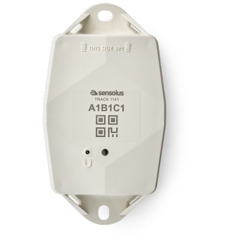
TRACK 1141
GNSS/BLE - NB-IoT
www.sensolus.com | info@sensolus.com
The rugged low-power tracker with long battery life
with NB-IoT connectivity and guaranteed data
recovery. The tracker provides general localization,
zone and high precision. The tracker firmware can be
upgraded over the air.
GNSS
Bluetooth geobeacon for zone precision
NB-IoT
Europe and North America
Data recovery
IP69K & IP68
IK 09
Flame retardant
130×72×36 mm
212g (7.6 oz)
Connectivity
NB-IoT
•
Energy efficient transceiver
•
Internal omnidirectional antenna
•
Bi-directional communication
•
NB-IoT bands: Europe/North America
•
Data recovery
•
OTA firmware upgrade (NB-IoT)
Bluetooth Low Energy (BLE)
Bluetooth Low Energy 5.0
Geolocalization
GNSS
Multi GNSS constellation chipset (GPS+GALILEO)
BLE
•
Sensolus proximity beacon detection
•
Detectable by zone and high precision anchors
Sensing
Internal
•
Activity monitoring
•
Orientation monitoring
•
Virtual tamper detection
Activation and mounting
•
Activation manual link
•
Holes 7x9mm for screws or rivets. 115 mm distance
between the centers of the mounting holes.
•
Instructions for mounting the device can be found here.TRACK 1141
GNSS/BLE - NB-IoT
www.sensolus.com | info@sensolus.com
Mechanics & Design
Antennas
All antennas are internal
Water & dust resistance
IP68 & IP69K
Size
130x72x36 mm(LWH))
Impact resistance
IK09
Weight
212 gram (7.6 oz)
Drop shock and vibration
EN 60068
Color
White
Operating temperature
-20°C to 60°C*
The specifics regarding operational temperature are contingent upon the
application, installation circumstances, and environmental factors such as
sunlight exposure. For further information, please reach out to Sensolus.
Battery life can be affected when devices function for extended periods at the
extremes of this range.
Casing
•
Shell: PBT + PC Cover: PBT GF30% + TPE
•
Flame retardant
•
UV-stabilized
Battery
Standard 3 cell
•
User replaceable battery pack (Li-SoCl₂) 10500 mAh
•
2.94 gram lithium
Certifications
Regulatory
•
CE
•
FCC
Bluetooth 5.0
Declaration ID D068598
Electrical safety
EN 62368-1
User Interaction
Device activation
Magnetic activation
LED feedback
Green & red LED feedback on the device
Synchronize remote settings
•
Instant: Magnet activation
•
Periodic: No user interaction neededTRACK 1141
GNSS/BLE - NB-IoT
www.sensolus.com | info@sensolus.com
Management Services
Diagnostics
•
Battery lifetime prediction
•
Detailed energy consumption
•
Geolocation diagnostics
•
Installation
•
Communication quality
Management
•
OTA firmware updates over NB-IoT and BLE
•
Remote configuration
•
Tracker usage profiles
Application services
•
Localization
•
Journeys
•
Activity
•
Utilization
Firmware configuration
Communication service
•
Data recovery strategy
•
Communication conditions
Location service
•
Motion based, periodic or scheduled
•
Configurable update rate and journey detection
•
Priority sequence (GNSS, Bluetooth geobeacon)
•
GNSS fix parameters
•
Indoor detection algo
•
BLE scan strategy
General configuration
•
Rule engine configuration
•
Diagnostic levels
•
Boot methods
•
Accurate time synchronization
Orientation service
Orientation detection parameters
Activity service
Activity detection parameters
Tamper service
Virtual tamper algo configuration
Security
•
Device unique encryption keys
•
End to end payload encryption Chacha 20
•
AES encrypted firmware
•
Firmware upgrade allows only signed firmware images
Installation and activation manual TRACK 1101 and TRACK 1141 (pdf)
Installation and activation manual TRACK 1101 and TRACK 1141 (pdf)
Description:
Access level: public
Reference: SDOC-498608282-1392
Download: PDF
Access level: public
Reference: SDOC-498608282-1392
Download: PDF
Installation and activation manual
TRACK 1101 and TRACK 1141
www.sensolus.com | info@sensolus.com
November 21, 2025 9:47 AM
Mounting the tracker
Guidelines how to mount the tracker can be found here.
Tracker activation
Activation of the trackers is preferably done with clear skies, and not inside (e.g. factory or warehouse).
Trackers are not activated when delivered to your premises.
Their subscription in the platform will start within six months of purchase.
1
Hold a magnet for
about 5 seconds on
top of the logo on the
asset tracker.
→
2
You will first see a red
LED. Do not remove
the magnet yet.
→
3
When the green LED
is blinking you can
remove the magnet.
Your tracker is ready
for use.
Activation troubleshooting
Activating a tracker that communicates over the NB-IoT or LTE-M network can sometimes come with a delay. With a delay we
mean that the online status doesn't appear within 5 minutes after holding the magnet to the tracker. This is mostly due to
conditions on the network operator site.
If the activation wasn't successful after 5 minutes the tracker will try again to activate again after waiting 24 hours.
This long period of time is often an obstacle to start installing trackers to assets and makes the timing of the installation of the
trackers cumbersome as it is important to only install trackers when they appeared as online on the platform.
To overcome to 24 hours waiting time, you can do the following:
If after 5 minutes of waiting and the status didn't change yet to “online” hold the magnet again for 5 seconds on top of the
tracker to enforce a new attempt for activation. Keep trying every 5 minutes until the Online status appears.
Installation advice
Avoid blocking the tracker's view
with metal or carbonfibre walls.
They weaken or block the
radiofrequency signals.
Place the tracker as high as
possible on the asset to ensure
good network coverage.
Make sure the mounting surface
is flat and clean, for a strong and
durable bond.
Do not install the tracker on
parts that receive frequent
shocks or vibrations.Installation and activation manual
TRACK 1101 and TRACK 1141
www.sensolus.com | info@sensolus.com
November 21, 2025 9:47 AM
Install the tracker vertically, with
the logo facing up.
If your asset is handled in a rough
environment, you can place the
tracker in a protected location,
but never with metal or
carbonfibre above the tracker.
Make sure the tracker has a clear
view on the sky.
Avoid placing the tracker in a
place that can collect water.
If you can't install vertically, do
not mount the tracker upside
down.
It is advisable to place a thermal
insulation material, such as wood
or plastic, between the tracker
and the metal asset if the latter is
subjected to prolonged exposure
to sunlight.
Troubleshooting
- Put the magnet on the tracker for less than 5 seconds
- The possible LED feedback options are: Red LED: Tracker is not activated Green LED: Tracker is activated and working properly No LED: tracker is not functioning (probably dead battery -> contact support) Red LED is blinking: Tracker is busy
- This device may not cause harmful interference, and
- This device must accept any interference received, including interference that may cause undesired operation. This equipment has been tested and found to comply with the limits for a Class B digital device, pursuant to Part 15 of the FCC Rules. These limits are designed to provide reasonable protection against harmful interference in a residential installation. This equipment generates, uses and can radiate radio frequency energy and, if not installed and used in accordance with the instructions, may cause harmful interference to radio communications. However, there is no guarantee that interference will not occur in a particular installation. If this equipment does cause harmful interference to radio or television reception, which can be determined by turning the equipment off and on, the user is encouraged to try to correct the interference by one of the following measures: • Reorient or relocate the receiving antenna. • Increase the separation between the equipment and receiver. • Connect the equipment into an outlet on a circuit different from that to which the receiver is connected. • Consult the dealer or an experienced radio/TV technician for help. FCC Caution: Any changes or modifications not expressly approved by the party responsible for compliance could void the user's authority to operate this equipment. This transmitter must not be co-located or operating in conjunction with any other antenna or transmitter. Radiation Exposure Statement: This equipment complies with FCC radiation exposure limits set forth for an uncontrolled environment. This equipment should be installed and operated with minimum distance 20cm between the radiator & your body. This equipment is not suitable for use in locations where children are likely to be present. Industry Canada Statement This device complies with ISED's licence-exempt RSSs. Operation is subject to the following two conditions: This device may not cause harmful interference, and This device must accept any interference received, including interference that may cause undesired operation. Under Industry Canada regulations, this radio transmitter may only operate using an antenna of a type and maximum (or lesser) gain approved for the transmitter by Industry Canada. To reduce potential radio interference to other users, the antenna type and its gain should be chosen so that the equivalent isotropically radiated power (e.i.r.p.) is not more than that necessary for successful communication. RF Exposure Requirements: This equipment complies with Canada radiation exposure limits set forth for an uncontrolled environment. This equipment should be installed and operated with minimum distance 20cm between the radiator and your body. Le présent appareil est conforme aux CNR d' ISED applicables aux appareils radio exempts de licence. L'exploitation est autorisée aux deux conditions suivantes:
- le dispositif ne doit pas produire de brouillage préjudiciable, et
- ce dispositif doit accepter tout brouillage reçu, y compris un brouillage susceptible de provoquer un fonctionnement indésirable. Conformément à la réglementation d'Industrie Canada, le présent émetteur radio peut fonctionner avec une antenne d'un type et d'un gain maximal (ou inférieur) approuvé pour l'émetteur par Industrie Canada. Dans le but de réduire les risques de brouillage radio électrique à l'intention des autres utilisateurs, il faut choisir le type d'antenne et son gain de sorte que la puissance isotrope rayonnée équivalente (p.i.r.e.) ne dépasse pas l'intensité nécessaire à l'établissement d'une communication satisfaisante. Déclaration d'exposition aux radiations: Cet équipement est conforme aux limites d'exposition aux rayonnements du Canada établies pour un environnement non contrôlé. Cet équipement doit être installé et utilisé avec un minimum de 20 cm de distance entre la source de rayonnement et votre corps.