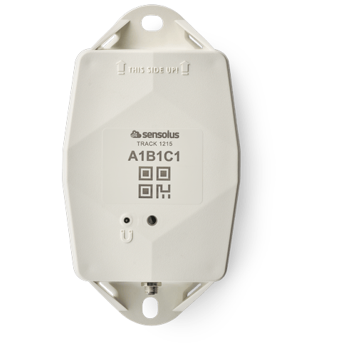
**Description**:
**Access level**: public
**Reference**: SDOC-498608282-1344
**Download**: [PDF](https://cloud.sensolus.com/documentation/dms/SDOC-498608282-1344)
TRACK 1215
GNSS/Wi-Fi/BLE - NB-IoT/LTE-M
[www.sensolus.com](http://www.sensolus.com) | [info@sensolus.com](mailto:info@sensolus.com)
Deploy this tracker connected to the vehicle power
source, or only use the internal backup battery to avoid
the wiring effort. It has NB-IoT and LTE-M
connectivity and guaranteed data recovery. Provides
outdoor and indoor localization. Supports external BLE
sensors. Acts as smart BLE gateway to locate
BLE-tagged assets transported by the vehicle.
GNSS
Wi-Fi scanning
Bluetooth geobeacon for zone precision
NB-IoT
LTE-M
Connectivity EXTENDED plan
Data recovery
Large internal backup battery
IP67
IK 09
Flame retardant
130×72×36 mm
212g (7.6 oz)
Connectivity
NB-IoT and LTE-M
•
Energy efficient transceiver
•
Internal omnidirectional antenna
•
Bi-directional communication
•
Data recovery
•
OTA firmware upgrade (NB-IoT and LTE-M)
Bluetooth Low Energy (BLE)
Bluetooth Low Energy 5.0
Connectivity plan
TRACK 1215 comes with the Extended connectivity plan
Geolocalization
GNSS
Multi GNSS constellation chipset (GPS+GALILEO)
BLE Geobeacon
•
Sensolus geobeacon detection
Wi-Fi scanning
•
Wi-Fi based geolocalization
TRACK 1215
GNSS/Wi-Fi/BLE - NB-IoT/LTE-M
[www.sensolus.com](http://www.sensolus.com) | [info@sensolus.com](mailto:info@sensolus.com)
Sensing
Internal
•
Activity monitoring
•
Orientation monitoring
•
Virtual tamper detection
•
Temperature monitoring
•
range: -20°C till 60°C (-4°F to 140°F)
•
typical accuracy: +/- 0.25°C (+/- 0.45°F)
•
worst case accuracy: +/- 1°C (+/- 1.8°F)
•
Configurable shock detection
Accessory BLE sensors
•
Temperature, humidity
•
Fill level, contact, magnet
•
Other BLE sensors can be added
Activation and mounting
•
Activation manual
•
Holes 7x9mm (⁹/₃₂ \* ²³/₆₄ in) for screws or rivets. 115 mm
(4¹⁷/₃₂ in) distance between the centers of the mounting
holes.
•
Instructions for mounting the device can be found here.
Mechanics & Design
Antennas
All antennas are internal
Water & dust resistance
IP67
Size
130x72x36 mm
(5⅛ x 2⁵³⁄₆₄ x 1²⁷⁄₆₄ in)
Impact resistance
IK09
Weight
218 gram (7.68 oz) without cable
Drop shock and vibration
EN 60068
Color
White and black
Operating temperature
-20°C to 60°C
(-4°F to 140°F)\*
Casing
•
PBT/PC 29 TM-Z2 FR UV LS
•
Flame retardant
•
UV-stabilized
Power supply
Voltage
Input voltage: 10 - 30 V DC with overvoltage protection
Typical power consumption
\~3mA (idle)
Cable terminations
Connectors to the power source can be soldered to the cable
ends
Max typical power consumption
•
300mA (@10V)
•
70mA (@30V)
Fuse recommendations
•
\> 500mA and \< 1A fuse
•
The TRACK 1215 contains a non-resettable 1A slow blow
fuse (Bel fuse 0685T1000) at its external power input.
TRACK 1215
GNSS/Wi-Fi/BLE - NB-IoT/LTE-M
[www.sensolus.com](http://www.sensolus.com) | [info@sensolus.com](mailto:info@sensolus.com)
Back up battery
Standard 3 cell
•
Battery life depending on operating mode.
•
User replaceable battery pack (Li-SoCl₂) 12000 mAh
•
2.94 gram (0.1037oz) lithium
Certifications
Regulatory
•
CE
•
FCC
•
IC
Bluetooth 5.0
Declaration ID D068598
Environmental
Drop shock
Electrical safety
EN 62368-1
User Interaction
Device activation
Magnetic activation
LED feedback
Green & red LED feedback on the device
Synchronize remote settings
•
Instant: Magnet activation
•
Periodic: No user interaction needed
Management Services
Diagnostics
•
Battery lifetime prediction
•
Detailed energy consumption
•
Geolocation diagnostics
•
Installation
•
Communication quality
Management
•
OTA firmware updates over NB-IoT,LTE-M and BLE
•
Remote configuration
•
Tracker usage profiles
•
External environmental sensors
Application services
•
Localization
•
Journeys
•
Activity
•
Utilization
•
Connectable with environmental sensors
•
Temperature detection
•
Tilt detection
•
Shock detection
TRACK 1215
GNSS/Wi-Fi/BLE - NB-IoT/LTE-M
[www.sensolus.com](http://www.sensolus.com) | [info@sensolus.com](mailto:info@sensolus.com)
Firmware configuration
Communication service
•
Data recovery strategy
•
Communication conditions
Location service
•
Motion based,context based, periodic or scheduled
•
Configurable update rate and journey detection
•
Priority sequence (GNSS, Wi-Fi scanning , Bluetooth
geobeacon)
•
GNSS fix parameters
•
Indoor detection algo
•
Wi-Fi scan strategy
•
BLE scan strategy
General configuration
•
Rule engine configuration
•
Diagnostic levels
•
Boot methods
•
Accurate time synchronization
Orientation service
Orientation detection parameters
Environmental sensing
•
Polling and aggregation strategy
•
Alerts
•
Edge processing parameters
Activity service
Activity detection parameters
Tamper service
Virtual tamper algo configuration
Shock detection
Shock algo detection parameters
Security
•
Device unique encryption keys
•
End to end payload encryption Chacha 20
•
AES encrypted firmware
•
Firmware upgrade allows only signed firmware images
Accessories
CAB 8600: 6 m power cable for TRACK 1215
**Description**:
**Access level**: public
**Reference**: SDOC-498608282-1402
**Download**: [PDF](https://cloud.sensolus.com/documentation/dms/SDOC-498608282-1402)
Installation manual TRACK 1215
for BLE tag scanning in vehicles
[www.sensolus.com](http://www.sensolus.com) | [info@sensolus.com](mailto:info@sensolus.com)
January 19, 2026
Tracker activation
Activation of the tracker is preferably done with clear skies, and not inside (e.g. factory or warehouse).
Trackers are not activated when delivered to your premises.
Their subscription in the platform will start within six months of purchase.
1
Hold a magnet for
about 5 seconds on
top of the logo on the
tracker.
→
2
You will first see a red
LED. Do not remove
the magnet yet.
→
3
When the green LED
is blinking you can
remove the magnet.
The tracker is ready
for use.
Activation troubleshooting
Activating a tracker that communicates over the NB-IoT network can sometimes come with a delay. With a delay we mean
that the online status doesn\'t appear within 5 minutes after holding the magnet to the tracker. This is mostly due to conditions
on the network operator site.
If the activation wasn\'t successful after 5 minutes the tracker will try again to activate again after waiting 24 hours.
This long period of time is often an obstacle to start installing trackers to assets and makes the timing of the installation of the
trackers cumbersome as it is important to only install trackers when they appeared as online on the platform.
To overcome the 24 hours waiting time, you can do the following:
If after 5 minutes of waiting and the status didn\'t change yet to "online" hold the magnet again for 5 seconds on top of the
tracker to enforce a new attempt for activation. Keep trying every 5 minutes until the Online status appears.
General installation advice
If your asset is handled in
a rough environment, you
can place the tracker in a
protected location, but
never with metal or
carbonfibre above the
tracker.
Place the tracker as high
as possible on the asset to
ensure good network
coverage.
Make sure the mounting
surface is flat and clean,
for a strong and durable
bond.
Do not install the tracker
on parts that receive
frequent shocks or
vibrations.
Avoid placing the tracker
in a place that can collect
water.
Installation manual TRACK 1215
for BLE tag scanning in vehicles
[www.sensolus.com](http://www.sensolus.com) | [info@sensolus.com](mailto:info@sensolus.com)
January 19, 2026
Preparing the installation in the vehicle
Tools and equipment
Enough 2 wire cable
Steel fish tape
Cable duct
Male and female spade
connectors
Fork connectors
Cable protector
Wire cutter
Screwdriver
Double sided tape
Wrench set
Stanley knife
Electrical fuse (> 500mA
and \< 1A)
Before the actual wiring
1. The tracker should be mounted in the middle of the truck or van.
2. Detect the best possible path from the vehicle\'s power source to the place of tracker installation. Estimate the amount
of wire needed to cover the complete path.
3. Make sure the 2 wire cable can pass everywhere, use the steel fish tape to test.
Installation manual TRACK 1215
for BLE tag scanning in vehicles
[www.sensolus.com](http://www.sensolus.com) | [info@sensolus.com](mailto:info@sensolus.com)
January 19, 2026
Installing the tracker
Wiring the truck
1. Route the cable: Use the steel fish tape to pull the wire through the available shafts of the truck. Preferably work from
the ground up. This might take a while, take your time. Make sure not to damage the cable.
2. Prepare the cable length: Make sure there is enough 2 wired cable to go to the vehicle\'s power source. Do not connect
anything to the power source yet.
3. Protect the cable: Protect the 2 cable wire where needed:
• Use cable duct and double sided tape for the inside of the van or truck.
• Use cable protector for the outside of the van or truck.
Cable duct inside the van or truck
Cable protector outside the truck
4. Install the fuse: An additional fuse (> 500mA and \< 1A) can be installed. Install the fuse on the voltage in red cable in
series. The tracker has an internal fuse, see specsheet for details.
Installation manual TRACK 1215
for BLE tag scanning in vehicles
[www.sensolus.com](http://www.sensolus.com) | [info@sensolus.com](mailto:info@sensolus.com)
January 19, 2026
The external cable is composed of 4 internal wires:
• Black: GND / Ground. Connect to black battery terminal (negative, minus sign).
• Red: VIN External voltage in. Connect to red battery terminal (positive, plus sign).
• Blue: Digital In / Analog In (not in use currently; pending a future firmware release).
• White: Digital Out (not in use currently; pending a future firmware release).
1. Install connectors on the vehicle wiring: Install the female spade connectors on the installed wires on the inside of the
truck.
2. Install connectors near the power source: Install the fork connectors to the end of the 2 wired cable near the power
source. Do not attach to the battery yet.
3. Install connectors on the tracker cable: Install the male spade connectors on the tracker cable.
Mounting the tracker
Guidelines how to mount the tracker can be found here.
Mount the tracker in such a way that you have good access and a good view to the power plug of the tracker.
Wrong: No view on tracker plug
Correct: Good view on tracker plug
Power the tracker
Attach the fork connectors to the vehicle\'s battery. The tracker is now powered.
Installation manual TRACK 1215
for BLE tag scanning in vehicles
[www.sensolus.com](http://www.sensolus.com) | [info@sensolus.com](mailto:info@sensolus.com)
January 19, 2026
1
Put the cable onto the
connector. Only the
black plastic piece will
go into the connector.
Do not force this.
→
2
Tighten the
connection by gently
screwing the cable
into the connector.
Do not force this.
→
3
Check if the power
cable is connected
well.
Force new configuration download on the tracker
A firmware can be uploaded on the tracker. Queue the firmware in the Sensolus platform first.
1
Hold a magnet for
about 5 seconds on
top of the logo on the
asset tracker. You will
see a green LED.
→
2
You will see a red and
green LED. Now
remove the magnet.
→
3
Green LED is blinking
for minimum 30
seconds. Your tracker
is checking for new
configurations.
→
You see a red LED:
No new
configuration
received.
You see a green
LED: New
configuration setting
received.
Troubleshooting
1. Put the magnet on the tracker for less than 5 seconds
2. The possible LED feedback options are:
Red LED: Tracker is not activated
Green LED: Tracker is activated
and working properly
No LED: Tracker is not
functioning (probably dead
battery -> contact support)
Red LED is blinking: Tracker is
busy
Installation manual TRACK 1215
for BLE tag scanning in vehicles
[www.sensolus.com](http://www.sensolus.com) | [info@sensolus.com](mailto:info@sensolus.com)
January 19, 2026
Regulatory Information
Federal Communication Commission Interference Statement
This device complies with Part 15 of the FCC Rules. Operation is subject to the following two conditions:
1. This device may not cause harmful interference, and
2. This device must accept any interference received, including interference that may cause undesired operation.
This equipment has been tested and found to comply with the limits for a Class B digital device, pursuant to Part 15 of the FCC Rules. These limits are designed to
provide reasonable protection against harmful interference in a residential installation. This equipment generates, uses and can radiate radio frequency energy and,
if not installed and used in accordance with the instructions, may cause harmful interference to radio communications. However, there is no guarantee that
interference will not occur in a particular installation. If this equipment does cause harmful interference to radio or television reception, which can be determined
by turning the equipment off and on, the user is encouraged to try to correct the interference by one of the following measures:
•
Reorient or relocate the receiving antenna.
•
Increase the separation between the equipment and receiver.
•
Connect the equipment into an outlet on a circuit different from that to which the receiver is connected.
•
Consult the dealer or an experienced radio/TV technician for help.
FCC Caution: Any changes or modifications not expressly approved by the party responsible for compliance could void the user\'s authority to operate this
equipment.
This transmitter must not be co-located or operating in conjunction with any other antenna or transmitter.
Radiation Exposure Statement:
This equipment complies with FCC radiation exposure limits set forth for an uncontrolled environment.
This equipment should be installed and operated with minimum distance 20cm between the radiator & your body.
This equipment is not suitable for use in locations where children are likely to be present.
Industry Canada Statement
This device complies with ISED\'s licence-exempt RSSs.
Operation is subject to the following two conditions:
This device may not cause harmful interference, and
This device must accept any interference received, including interference that may cause undesired operation.
Under Industry Canada regulations, this radio transmitter may only operate using an antenna of a type and maximum (or lesser) gain approved for the transmitter
by Industry Canada.
To reduce potential radio interference to other users, the antenna type and its gain should be chosen so that the equivalent isotropically radiated power (e.i.r.p.) is
not more than that necessary for successful communication.
RF Exposure Requirements:
This equipment complies with Canada radiation exposure limits set forth for an uncontrolled environment.
This equipment should be installed and operated with minimum distance 20cm between the radiator and your body.
Le présent appareil est conforme aux CNR d\' ISED applicables aux appareils radio exempts de licence.
L\'exploitation est autorisée aux deux conditions suivantes:
3. le dispositif ne doit pas produire de brouillage préjudiciable, et
4. ce dispositif doit accepter tout brouillage reçu, y compris un brouillage susceptible de provoquer un fonctionnement indésirable.
Conformément à la réglementation d\'Industrie Canada, le présent émetteur radio peut fonctionner avec une antenne d\'un type et d\'un gain maximal (ou inférieur)
approuvé pour l\'émetteur par Industrie Canada.
Dans le but de réduire les risques de brouillage radio électrique à l\'intention des autres utilisateurs, il faut choisir le type d\'antenne et son gain de sorte que la
puissance isotrope rayonnée équivalente (p.i.r.e.) ne dépasse pas l\'intensité nécessaire à l\'établissement d\'une communication satisfaisante.
Déclaration d\'exposition aux radiations:
Cet équipement est conforme aux limites d\'exposition aux rayonnements du Canada établies pour un environnement non contrôlé.
Cet équipement doit être installé et utilisé avec un minimum de 20 cm de distance entre la source de rayonnement et votre corps.
Installation manual TRACK 1215
for BLE tag scanning in vehicles
[www.sensolus.com](http://www.sensolus.com) | [info@sensolus.com](mailto:info@sensolus.com)
January 19, 2026
Safety advice – device subjected to strong mechanical impact
Risk of delayed battery failure and chemical hazard
If a device has been hit, crushed, or struck by a heavy object (for example a forklift, container, pallet, or falling load), the
internal components and battery may be damaged even if no external damage is visible. Such damage can result in delayed
overheating, leakage, or failure.
If a device has been subjected to a strong mechanical impact, the following mandatory safety actions must be taken:
\#
Action
Details
1
Do not touch the device
Do not move, lift, open, shake, or inspect the
device immediately after the impact. Internal
damage may cause delayed reactions.
2
Keep a minimum safety distance
Maintain a clear distance of at least 5 meters
from the device. Keep all personnel away
during this period.
3
Wait at least 10 minutes
The device must remain untouched and
undisturbed for a minimum of 10 minutes
following the impact. This waiting time
allows potential delayed thermal or chemical
reactions to become evident.
4
Observe from a safe distance
Watch for warning signs: smoke, vapor, or
unusual odor; heat generation; fluid leakage;
hissing, cracking, or popping noises.
5
After the waiting period
If any abnormal condition is observed,
isolate the area immediately and notify
responsible safety or supervisory personnel.
The device must be quarantined and
handled according to battery safety and
disposal procedures. The device must not be
used.
A device may appear undamaged and still be unsafe. Normal operation after impact does NOT mean the device is safe.
Failure to follow this safety advice may result in serious injury, fire, or chemical exposure.
**Description**:
**Access level**: public
**Reference**: SDOC-498608282-1403
**Download**: [PDF](https://cloud.sensolus.com/documentation/dms/SDOC-498608282-1403)
Installation manual TRACK 1215
[www.sensolus.com](http://www.sensolus.com) | [info@sensolus.com](mailto:info@sensolus.com)
January 19, 2026
Tracker activation
Activation of the tracker is preferably done with clear skies, and not inside (e.g. factory or warehouse).
Trackers are not activated when delivered to your premises.
Their subscription in the platform will start within six months of purchase.
1
Hold a magnet for
about 5 seconds on
top of the logo on the
tracker.
→
2
You will first see a red
LED. Do not remove
the magnet yet.
→
3
When the green LED
is blinking you can
remove the magnet.
The tracker is ready
for use.
Activation troubleshooting
Activating a tracker that communicates over the NB-IoT network can sometimes come with a delay. With a delay we mean
that the online status doesn\'t appear within 5 minutes after holding the magnet to the tracker. This is mostly due to conditions
on the network operator site.
If the activation wasn\'t successful after 5 minutes the tracker will try again to activate again after waiting 24 hours.
This long period of time is often an obstacle to start installing trackers to assets and makes the timing of the installation of the
trackers cumbersome as it is important to only install trackers when they appeared as online on the platform.
To overcome the 24 hours waiting time, you can do the following:
If after 5 minutes of waiting and the status didn\'t change yet to "online" hold the magnet again for 5 seconds on top of the
tracker to enforce a new attempt for activation. Keep trying every 5 minutes until the Online status appears.
General installation advice
If your asset is handled in
a rough environment, you
can place the tracker in a
protected location, but
never with metal or
carbonfibre above the
tracker.
Place the tracker as high
as possible on the asset to
ensure good network
coverage.
Make sure the mounting
surface is flat and clean,
for a strong and durable
bond.
Do not install the tracker
on parts that receive
frequent shocks or
vibrations.
Avoid placing the tracker
in a place that can collect
water.
Installation manual TRACK 1215
[www.sensolus.com](http://www.sensolus.com) | [info@sensolus.com](mailto:info@sensolus.com)
January 19, 2026
Mount the tracker onto the vehicle
Guidelines how to mount the tracker can be found here. Mount the tracker in such a way you have good access and a good
view to the power plug of the tracker.
Installation manual TRACK 1215
[www.sensolus.com](http://www.sensolus.com) | [info@sensolus.com](mailto:info@sensolus.com)
January 19, 2026
Fuse installation and wiring
An additional fuse (> 500mA and \< 1A) can be installed. Install the fuse on the voltage in red cable in series. The tracker has an
internal fuse, see specsheet for details.
The external cable is composed of 4 internal wires:
• Black: GND / Ground. Connect to black battery terminal (negative, minus sign).
• Red: VIN External voltage in. Connect to red battery terminal (positive, plus sign).
• Blue: Digital In / Analog In (not in use currently; pending a future firmware release).
• White: Digital Out (not in use currently; pending a future firmware release).
1. Install connectors on the vehicle wiring: Install the female spade connectors on the installed wires on the inside of the
truck.
2. Install connectors near the power source: Install the fork connectors to the end of the 2 wired cable near the power
source. Do not attach to the battery yet.
3. Install connectors on the tracker cable: Install the male spade connectors on the tracker cable.
Installation manual TRACK 1215
[www.sensolus.com](http://www.sensolus.com) | [info@sensolus.com](mailto:info@sensolus.com)
January 19, 2026
Connect tracker to the vehicle power source
1
Put the cable onto the
connector. Only the
black plastic piece will
go into the connector.
Do not force this.
→
2
Tighten the
connection by gently
screwing the cable
into the connector.
Do not force this.
→
3
Check if the power
cable is connected
well.
Force new configuration download on the tracker
A firmware can be uploaded on the tracker. Queue the firmware in the Sensolus platform first.
1
Hold a magnet for
about 5 seconds on
top of the logo on the
asset tracker. You will
see a green LED.
→
2
You will see a red and
green LED. Now
remove the magnet.
→
3
Green LED is blinking
for minimum 30
seconds. Your tracker
is checking for new
configurations.
→
You see a red LED:
No new
configuration
received.
You see a green
LED: New
configuration setting
received.
Troubleshooting
1. Put the magnet on the tracker for less than 5 seconds
2. The possible LED feedback options are:
Red LED: Tracker is not activated
Green LED: Tracker is activated
and working properly
No LED: Tracker is not
functioning (probably dead
battery -> contact support)
Red LED is blinking: Tracker is
busy
Installation manual TRACK 1215
[www.sensolus.com](http://www.sensolus.com) | [info@sensolus.com](mailto:info@sensolus.com)
January 19, 2026
Regulatory Information
Federal Communication Commission Interference Statement
This device complies with Part 15 of the FCC Rules. Operation is subject to the following two conditions:
1. This device may not cause harmful interference, and
2. This device must accept any interference received, including interference that may cause undesired operation.
This equipment has been tested and found to comply with the limits for a Class B digital device, pursuant to Part 15 of the FCC Rules. These limits are designed to
provide reasonable protection against harmful interference in a residential installation. This equipment generates, uses and can radiate radio frequency energy and,
if not installed and used in accordance with the instructions, may cause harmful interference to radio communications. However, there is no guarantee that
interference will not occur in a particular installation. If this equipment does cause harmful interference to radio or television reception, which can be determined
by turning the equipment off and on, the user is encouraged to try to correct the interference by one of the following measures:
•
Reorient or relocate the receiving antenna.
•
Increase the separation between the equipment and receiver.
•
Connect the equipment into an outlet on a circuit different from that to which the receiver is connected.
•
Consult the dealer or an experienced radio/TV technician for help.
FCC Caution: Any changes or modifications not expressly approved by the party responsible for compliance could void the user\'s authority to operate this
equipment.
This transmitter must not be co-located or operating in conjunction with any other antenna or transmitter.
Radiation Exposure Statement:
This equipment complies with FCC radiation exposure limits set forth for an uncontrolled environment.
This equipment should be installed and operated with minimum distance 20cm between the radiator & your body.
This equipment is not suitable for use in locations where children are likely to be present.
Industry Canada Statement
This device complies with ISED\'s licence-exempt RSSs.
Operation is subject to the following two conditions:
This device may not cause harmful interference, and
This device must accept any interference received, including interference that may cause undesired operation.
Under Industry Canada regulations, this radio transmitter may only operate using an antenna of a type and maximum (or lesser) gain approved for the transmitter
by Industry Canada.
To reduce potential radio interference to other users, the antenna type and its gain should be chosen so that the equivalent isotropically radiated power (e.i.r.p.) is
not more than that necessary for successful communication.
RF Exposure Requirements:
This equipment complies with Canada radiation exposure limits set forth for an uncontrolled environment.
This equipment should be installed and operated with minimum distance 20cm between the radiator and your body.
Le présent appareil est conforme aux CNR d\' ISED applicables aux appareils radio exempts de licence.
L\'exploitation est autorisée aux deux conditions suivantes:
3. le dispositif ne doit pas produire de brouillage préjudiciable, et
4. ce dispositif doit accepter tout brouillage reçu, y compris un brouillage susceptible de provoquer un fonctionnement indésirable.
Conformément à la réglementation d\'Industrie Canada, le présent émetteur radio peut fonctionner avec une antenne d\'un type et d\'un gain maximal (ou inférieur)
approuvé pour l\'émetteur par Industrie Canada.
Dans le but de réduire les risques de brouillage radio électrique à l\'intention des autres utilisateurs, il faut choisir le type d\'antenne et son gain de sorte que la
puissance isotrope rayonnée équivalente (p.i.r.e.) ne dépasse pas l\'intensité nécessaire à l\'établissement d\'une communication satisfaisante.
Déclaration d\'exposition aux radiations:
Cet équipement est conforme aux limites d\'exposition aux rayonnements du Canada établies pour un environnement non contrôlé.
Cet équipement doit être installé et utilisé avec un minimum de 20 cm de distance entre la source de rayonnement et votre corps.
Installation manual TRACK 1215
[www.sensolus.com](http://www.sensolus.com) | [info@sensolus.com](mailto:info@sensolus.com)
January 19, 2026
Safety advice – device subjected to strong mechanical impact
Risk of delayed battery failure and chemical hazard
If a device has been hit, crushed, or struck by a heavy object (for example a forklift, container, pallet, or falling load), the
internal components and battery may be damaged even if no external damage is visible. Such damage can result in delayed
overheating, leakage, or failure.
If a device has been subjected to a strong mechanical impact, the following mandatory safety actions must be taken:
\#
Action
Details
1
Do not touch the device
Do not move, lift, open, shake, or inspect the
device immediately after the impact. Internal
damage may cause delayed reactions.
2
Keep a minimum safety distance
Maintain a clear distance of at least 5 meters
from the device. Keep all personnel away
during this period.
3
Wait at least 10 minutes
The device must remain untouched and
undisturbed for a minimum of 10 minutes
following the impact. This waiting time
allows potential delayed thermal or chemical
reactions to become evident.
4
Observe from a safe distance
Watch for warning signs: smoke, vapor, or
unusual odor; heat generation; fluid leakage;
hissing, cracking, or popping noises.
5
After the waiting period
If any abnormal condition is observed,
isolate the area immediately and notify
responsible safety or supervisory personnel.
The device must be quarantined and
handled according to battery safety and
disposal procedures. The device must not be
used.
A device may appear undamaged and still be unsafe. Normal operation after impact does NOT mean the device is safe.
Failure to follow this safety advice may result in serious injury, fire, or chemical exposure.
For installation instructions, see [Installation instructions](/docs/spec_sheets/installation_instructions).
## TRACK 1215 cable wiring
### External power source - cable wiring
The cable provided with TRACK 1215 has a length of 2 meters. The cable allows connecting the tracker to a power source of a vehicle (car / truck / trailer battery).
A cable of 6 meters can be purchased separately.